Mold Delrin® Gears with Precision

One of the main considerations for molding a gear is dimensional accuracy and roundness.
In most gear applications, unreinforced grades of Delrin® are used, which gives a big advantage over a glass reinforced material since it has more even shrinkage in respect to the flow direction. Glass reinforced materials, on the other hand, demonstrate high shrinkage perpendicular to the glass fiber and low shrinkage in the flow direction. This uneven shrinkage can result in part distortion (warpage) and loss of roundness.
That said, there are still important factors that need to be considered to optimize dimensional stability when molding gears in Delrin®:
- Gate location and filling pattern
- Design features that influence shrinkage
- Part packing by feeding in more material to take up the shrinkage from molten to solid
Gate location
The way the plastic fills the cavity of the tool should be studied to ensure the most even fill possible.
In an ideal case, the plastic fills the extremities of the gear at the same time, so with a circular gear that would suggest a center gate is the best option, but there is more to take into consideration.
Design features that influence shrinkage
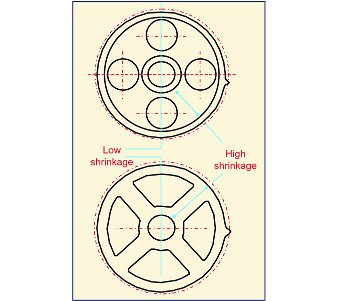
Studying the part filling pattern will also give an indication if any of the design features will impact the shrinkage of the part.
In these examples, there are cut-outs in the part to save weight. While lighter weight gears are desirable to improve system efficiency, in this case the design change meant different levels of shrinkage occurred around the holes, which contributed to an out-of-roundness at the teeth.

A similar effect could be observed by other design features that affect flow such as a thin rib that creates a flow hesitation or a thick section that has higher overall shrinkage, even if well packed which leads on to the next point.
Part Packing
Packing is the processing phase where more material is injected into the cavity to compensate for the contraction from molten to solid Delrin®.
It is critical to the performance and dimensional stability of a Delrin® component that it is fully packed during the injection molding process. If not, there will be high shrinkage and the risk of voids that could reduce the strength of the gear.
To ensure that the gear can be fully packed involves injecting into the thickest section with a gate and runner system that does not prematurely freeze.
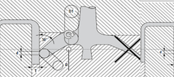
This is illustrated below:

On the right, the gate tapers too much and is fed into the thinnest section. The plastic material in this area will solidify first, while the material at the center of the thick section will still be molten. With no more material being fed into the part, there will be a high level of shrinkage resulting in sinking of the surface or voids in the center.
The design on the left allows more material to be fed into the thick section for longer in order to fully pack the part and avoid uncontrolled shrinkage. Diameter of the gate “d” must be at least half the part thickness, “T”. The length of the gate must be shorter than 0.8 mm. Diameter “D” of the runner next to the gate must be at least the part thickness “T”+1mm. “D1” should be larger than “D”. More information can be found in the Delrin Molding guide.
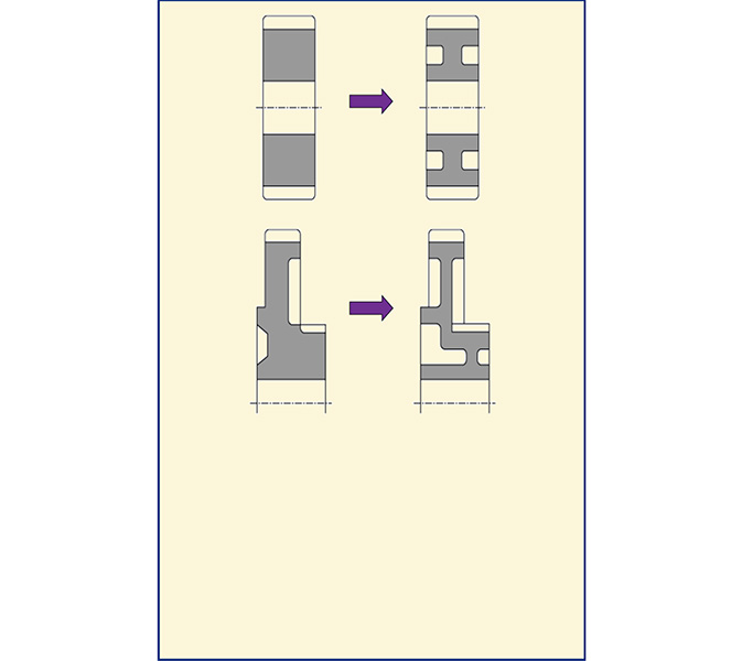
Below are some ideas to maintain an even wall thickness, which will ensure that a gear can be molded with an optimum cycle time.

Using a filling simulation software, such as Moldflow®, the molding cycle, packing, and part shrinkage can all be studied prior to making an injection molding tool. This is encouraged to ensure the correct decisions are being taken to optimise gear part.
Many grades of Delrin® are fully characterized for use in such simulation software.
